


A drill pipe tool joint is the thick-walled, threaded steel connector welded to each end of a drill pipe body. One end carries an external thread (the pin) and the other an internal thread (the box), so individual pipes can be screwed together into a drill string. Its heavier wall lets it withstand repeated make-up and break-out while carrying torque and axial load through the string.
This article covers how a drill pipe tool joint is built, how pin, box and shoulder work together, how OD, ID and wear affect torsional strength, and what to check when selecting one.
A tool joint is a forged steel connector that is welded to each end of a drill pipe body. One end receives a pin member and the other a box member, so every length of drill pipe has a box at one end and a pin at the other. When pipes are stacked in the string, the pin of one joint threads into the box of the next.
A complete drill pipe has three distinct parts: the drill pipe body, the tool joint at each end, and the weld zone where the two are joined. The body is a long, relatively thin-walled pipe. It spans the distance, carries the weight of the string below, transmits torque from surface to bit, and lets drilling fluid pass through. It is not a good place to cut threads, for three reasons:
Because its OD is larger than the pipe body, the tool joint commonly contacts the casing or hole wall first. That is why it often carries hardbanding, and why its wear matters later in this article.
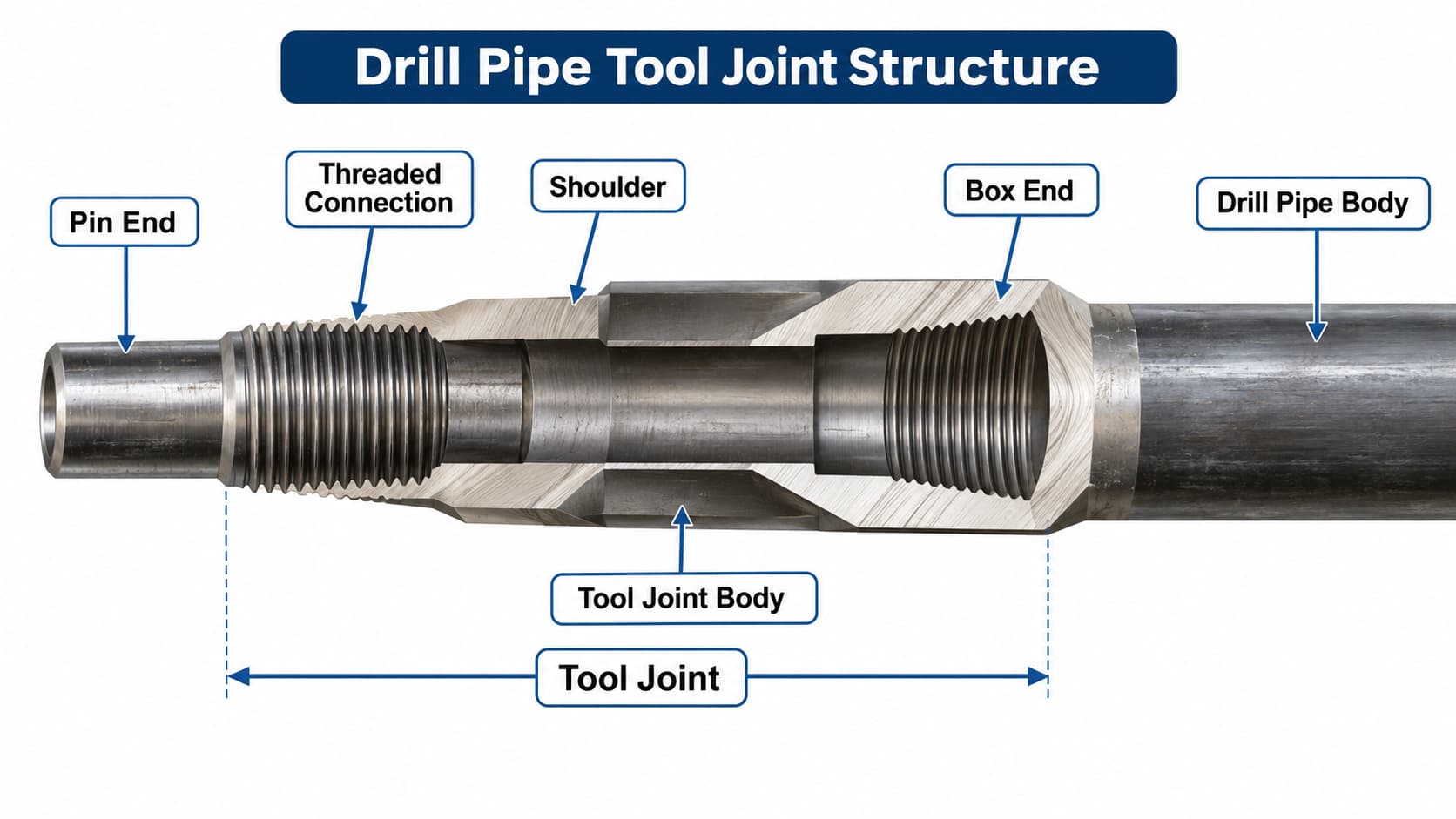
The structure of a drill pipe tool joint is simple, but each feature has a mechanical job, and the pin and box only work as a connection when all of them act together.
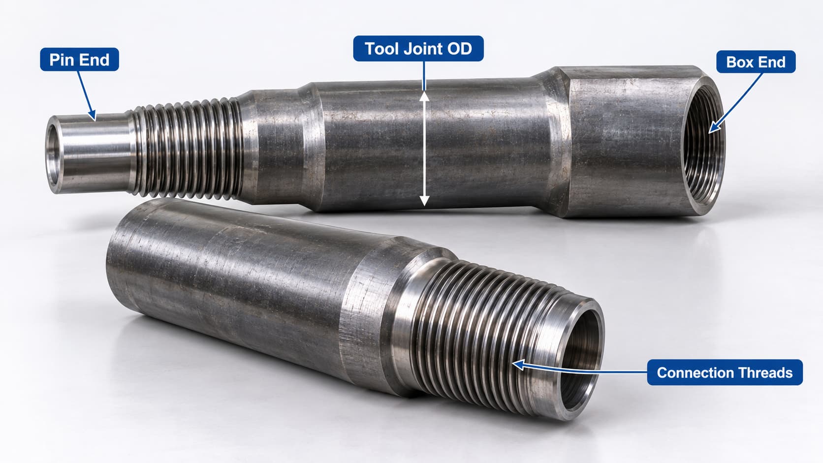
Pin end. The pin is the male member, with a tapered external thread. Its critical section is at the thread root, where the remaining wall depends on the bore diameter and the thread depth.
Box end. The box is the female member, with a matching tapered internal thread. Its wall is loaded in hoop tension by thread engagement and by the make-up preload. Its strength depends largely on how much steel remains between the thread root and the outside diameter, which is why box OD and wear are closely linked to torsional capacity.
Threaded connection. The tapered threads align the two members and provide the mechanical engagement that holds the connection together under axial load. Thread form, taper and pitch vary by connection design.
Shoulder. In API-style rotary shouldered connections, the primary shoulder is the contact between the box face and the pin base. Some proprietary designs add a second contact surface, so the shoulder arrangement depends on the connection design. When the connection is made up, the shoulder faces are pressed together. This contact creates the preload that keeps the connection tight, limits how much of the working load the threads carry alone, and forms the primary seal against drilling fluid. Shoulder condition therefore matters as much as the threads.
Tool joint body. This is the thick-walled forged section behind the threads on both the pin and the box. It provides the steel that supports the thread, tong space for make-up and break-out, tapered transitions at the weld end, and the surface for welding to the pipe.
|
Feature |
Pin |
Box |
|
Thread |
External, tapered |
Internal, tapered |
|
Critical section for torsional strength |
Wall between bore and thread root |
Wall between thread root and OD |
|
Effect of OD wear |
Little direct effect |
Reduces effective wall and can reduce strength |
|
Effect of ID |
Larger bore leaves less wall at the pin |
Less direct, since box wall is governed mainly by OD |
Tool joints are normally attached to the pipe body by friction welding. In this process, one part is rotated against the other under axial force. Friction heats the two faces until the steel is plastic, and the axial pressure then forges them together. After welding, the weld zone is heat treated and the weld flash is removed.
Three zones should be kept distinct in this region: the tool joint, which is the forged connector with threads and shoulders; the drill pipe body, the rolled and heat-treated main length of the pipe; and the weld zone, the narrow band where the two are fused. The weld zone is controlled through the manufacturer’s welding procedure and post-weld heat treatment. Its properties should not be assumed to equal those of either neighbor.
To strengthen the pipe end where the tool joint is attached, the wall is thickened before welding. This is called an upset. Three forms are used.
|
Upset type |
Where extra wall is added |
Structural result |
|
Internal upset (IU) |
Inside the pipe end |
Outside diameter stays the same as the pipe body; the bore narrows near the end |
|
External upset (EU) |
Outside the pipe end |
Bore stays the same as the pipe body; outside diameter increases near the end |
|
Internal-external upset (IEU) |
Both inside and outside |
Wall is thickened in both directions, with some change to both bore and outside diameter |
The choice affects the bore near the connection, the outside diameter, and the geometry available for the weld. It depends on pipe size, weight class, design standard and the manufacturer’s process. No single type is better in every case, because each trades off bore restriction, outside diameter and wall transition differently. The upset type is also usually paired with particular connection families; see our Drill Pipe Connection Types article.
In operation, the drill string is loaded in several ways at once. A tool joint has to connect adjacent pipes and carry a share of each load.
Connecting pipes. The threaded pin and box lock two lengths together and keep them aligned along the string axis.
Transmitting rotary torque. Torque from the top drive or rotary table is carried down through the whole string. Across each tool joint, it passes through the engaged threads and the pressed shoulder faces, and the make-up preload determines how well the shoulder contact does its part.
Carrying axial load. The string hangs from the surface, so each tool joint supports the weight below it. Axial tension passes through the threads, and the preload controls how that load is shared between thread and shoulder.
Preload and sealing. When the connection is made up, the pin is put in tension and the box shoulder in compression, with the shoulder faces pressed together. This keeps the shoulders in contact under working loads, so the connection does not open under bending or vibration, and it provides the seal that keeps drilling fluid inside the string.
Pin, box and shoulder act as a system. The threads provide engagement, the shoulder provides preload and seal, and the body behind each thread supplies the steel that carries load. If the shoulder is damaged or the preload is lost, the threads take a larger share of the load, and the connection becomes more vulnerable to fatigue and leakage.
Drill pipe tool joint torsional strength depends on the cross-sections of the pin and box, which are set by the OD, ID and thread geometry, together with the yield strength of the material. This is where tool joint dimensions have the most direct effect on how much torque a connection can carry.
What OD and ID mean. Tool joint OD is the outside diameter of the forged body. Tool joint ID is the bore through the connection. Both are set by the connection design and by the pipe size it is attached to. They are not the same as the pipe body dimensions: the tool joint is normally larger in OD and often smaller in ID.
Box OD and effective cross-section. The torque capacity of the box depends on the ring of steel between the root of its internal thread and its outside diameter. A larger OD, other things equal, increases this ring and raises the box’s capacity. If the OD is reduced, whether by design or by wear, the ring becomes thinner and the box has less material to resist the stresses from torque and make-up preload.
Pin ID and effective cross-section. The pin is limited from the other side. Its capacity depends on the steel between the pin’s bore and the root of its external thread. A larger bore removes steel from this section, so for a given connection design a larger ID generally means a smaller pin cross-section. A smaller ID leaves more steel in the pin but restricts flow and tool passage.
Pin weak and box weak. Because the pin and box have different critical sections, one will usually reach its limit before the other. A tool joint is “pin weak” when the pin’s capacity is lower than the box’s, and “box weak” when the box is lower. Pin weak and box weak can refer to tensile as well as torsional capacity; this article focuses on torsional strength. The overall torsional capacity of the connection is governed by the weaker member, because torque passes through both in series. The stronger side does not make up the difference.
This is why OD and ID cannot be judged separately. A larger OD helps the box but does nothing for a pin with a large bore. A small ID helps the pin but does not compensate for a box with worn OD. The resulting rating also depends on connection type, material yield strength and the manufacturer’s rating method, so specific values should be taken from the applicable standard or manufacturer data for the exact size, grade and connection.
Standard API tool joints are generally designed with a torsional strength below that of the pipe body they are welded to, so the connection, rather than the pipe body, is usually the torque-limiting element. Low-torque applications can accept a lower ratio, while high-torque drilling may call for connections with a higher torsional rating than the standard design. Check the rating of the specific connection rather than assuming it.
Bigger OD and smaller ID are not always better. A larger OD can improve box capacity and wear life, but it also reduces annular clearance, adds pressure loss outside the string, and may complicate fishing. A smaller ID can improve pin capacity but increases pressure loss inside the string and may limit tool or wireline access. The right dimensions depend on hole size, string design, material and loads.
Effect of OD wear. Tool joints contact the borehole and casing throughout drilling, and abrasion reduces their OD over time. Because the box depends on the steel between thread root and OD, wear directly reduces its effective cross-section and torsional capacity. A joint that was pin weak when new can become box weak as the OD wears, so a worn box may reach its limit sooner than its original rating suggests. Hardbanding slows this wear, but its condition also needs monitoring. For how wear is measured and judged, see our Drill Pipe Connection Inspection article.
Drill pipe make-up torque is the torque applied to tighten the pin into the box until the shoulders are pressed together with the intended preload. It is the means of setting that preload, so it decides whether the connection behaves as designed.
Too little torque. If make-up torque is too low, shoulder contact is weak. The connection can lose preload under bending, vibration or torque reversal, and the threads then take more of the load. This can lead to shoulder separation, leakage through the connection, thread wear and fatigue damage, and in severe cases a washout or a parted connection.
Too much torque. If torque is excessive, the pin can be stretched beyond its intended range and the box can be over-stressed. Shoulders can be damaged, threads can gall, and the connection may become difficult to break out.
Factors that affect the correct value. The appropriate torque is not a single universal number. Make-up torque is set mainly by the tool joint OD and ID, not by the dimensions or properties of the pipe body. For a given pin ID, a larger tool joint OD supports a higher make-up torque, and for a given OD, a larger pin ID lowers it. Standard values are calculated so that the weaker of the pin and box reaches a defined fraction of its minimum yield strength; the exact basis should be taken from the current API recommended practice or the manufacturer’s data.
Other factors include:
Because thread compound and surface condition change friction, the same torque reading can produce different preload in different conditions. Follow the manufacturer’s or applicable standard’s recommended torque for the specific tool joint, and use the compound for which that value was set. This article gives no torque figures, since they must be matched to the exact connection and conditions.
Selection works best as a sequence from well requirements to dimensions, then strength, then service life.
Tool joint OD and ID. Start from the hole size, casing program and hydraulic needs. Check that the OD fits the annular clearance and fishing requirements, and that the ID is large enough for the flow rate and for any tools that must pass. Then check how these dimensions move the weak side of the joint.
Connection type and thread compatibility. The connection must match the string, BHA and rig equipment.
Tensile and torsional strength. Compare the connection’s rated values with the expected loads, including drag, torque, bending and overpull margin. Check which side is the weak one, since that governs the torsional rating. For high-torque wells, confirm that the connection’s torsional rating, not just the pipe body’s, meets the requirement. Take ratings from current standards or manufacturer data for the exact size, grade and connection.
Drilling conditions. Deviated and extended-reach wells put more torque and bending on connections, and abrasive formations increase OD wear. Match the joint to these conditions, not just to nominal dimensions.
Wear resistance. Hardbanding and material hardness help the tool joint keep its OD, and therefore its box capacity, for longer.
Cost and service life. Compare cost over the expected service life rather than purchase price alone. Supplier documentation and traceability also matter when specifying a joint.
